How to Read the Italsensor Order Code
Every Italsensor encoder is identified by an alphanumeric order code that fully describes the product configuration. Being able to read this code lets you immediately understand what you are ordering — and compose a custom code for your application.
Code Structure
The code consists of 10 segments separated by dashes, each corresponding to a technical parameter:
[Type] - [Mounting] - [Resolution] - [Power Supply] - [Frequency] - [Protection] - [Shaft] - [Connection] - [Output] - [Custom]
Each segment has a precise meaning. Let us go through them one by one.
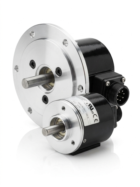
1. Type (Family + Flange + Direction)
The first segment identifies the encoder family, the flange type and whether it is unidirectional or bidirectional.
| Code | Meaning |
|---|---|
| TK510 | TK50, unidirectional (channel A only) |
| TK511 | TK50, unidirectional + Z pulse (zero ref.) |
| TK560 | TK50, bidirectional (channels A + B) |
| TK561 | TK50, bidirectional + Z pulse (zero ref.) |
The first digit after TK indicates the diameter (5 = Ø50 mm). The last digit: 0 = without Z pulse, 1 = with Z pulse (zero reference).
2. Mounting (Flange)
Defines the mechanical flange type for mounting.
| Code | Meaning |
|---|---|
| F | Standard servo flange |
| SG | Servo-clip |
| FRE | REO flange |
3. Resolution (PPR)
The number of pulses per revolution. Determines the angular precision of the encoder.
| Value | Positions/rev | Angular precision |
|---|---|---|
| 500 | 500 | 0.72° |
| 1000 | 1000 | 0.36° |
| 1024 | 1024 | 0.35° |
| 2048 | 2048 | 0.18° |
| 2500 | 2500 | 0.14° |
| 5000 | 5000 | 0.072° |
| 10000 | 10000 | 0.036° |
| 20000 | 20000 | 0.018° |
For absolute encoders, bits are used: 12 bits = 4096 positions/rev, 12/12 = 12 bits single-turn × 12 bits multi-turn.
4. Power Supply
The encoder's supply voltage.
| Code | Meaning |
|---|---|
| 5 | +5 Vdc (required for pure Line Driver) |
| 11/30 | +11–30 Vdc (industrial standard) |
| 24/5 | +11–30V with integrated +5V output |
5. Output Frequency
The maximum frequency of the output signal. Determines the maximum usable rotation speed.
| Code | Meaning |
|---|---|
| S | Standard: 0–100 kHz |
| V | Fast: 0–300 kHz |
The choice depends on the resolution × RPM ratio: frequency = PPR × RPM / 60.
6. Protection Class (IP)
The level of protection against dust and water according to IEC 60529.
| Code | IP Rating | Protection |
|---|---|---|
| K4 | IP64 | Total dust + water splashes |
| K5 | IP65 | Total dust + water jets |
| K6 | IP66 | Total dust + powerful jets |
7. Shaft Diameter
The solid shaft diameter in millimeters.
| Code | Meaning |
|---|---|
| 6 | Ø6 mm |
| 8 | Ø8 mm |
| 9.52 | Ø9.52 mm (3/8") |
| 10 | Ø10 mm |
| 11 | Ø11 mm (FRE flange) |
| 11R | Ø11 mm reduced (FRE flange) |
For hollow shaft encoders, the diameter indicates the through-bore size.
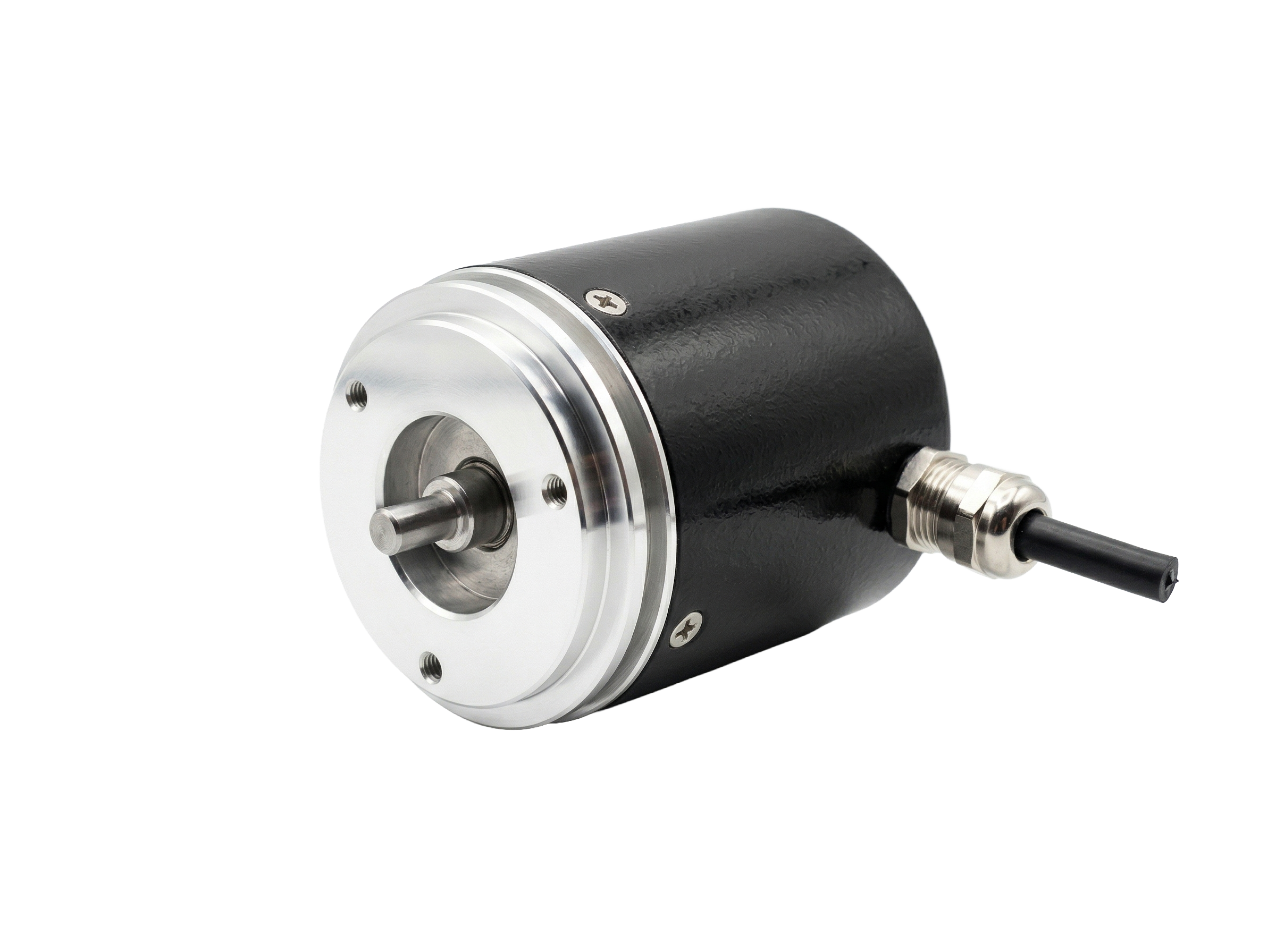
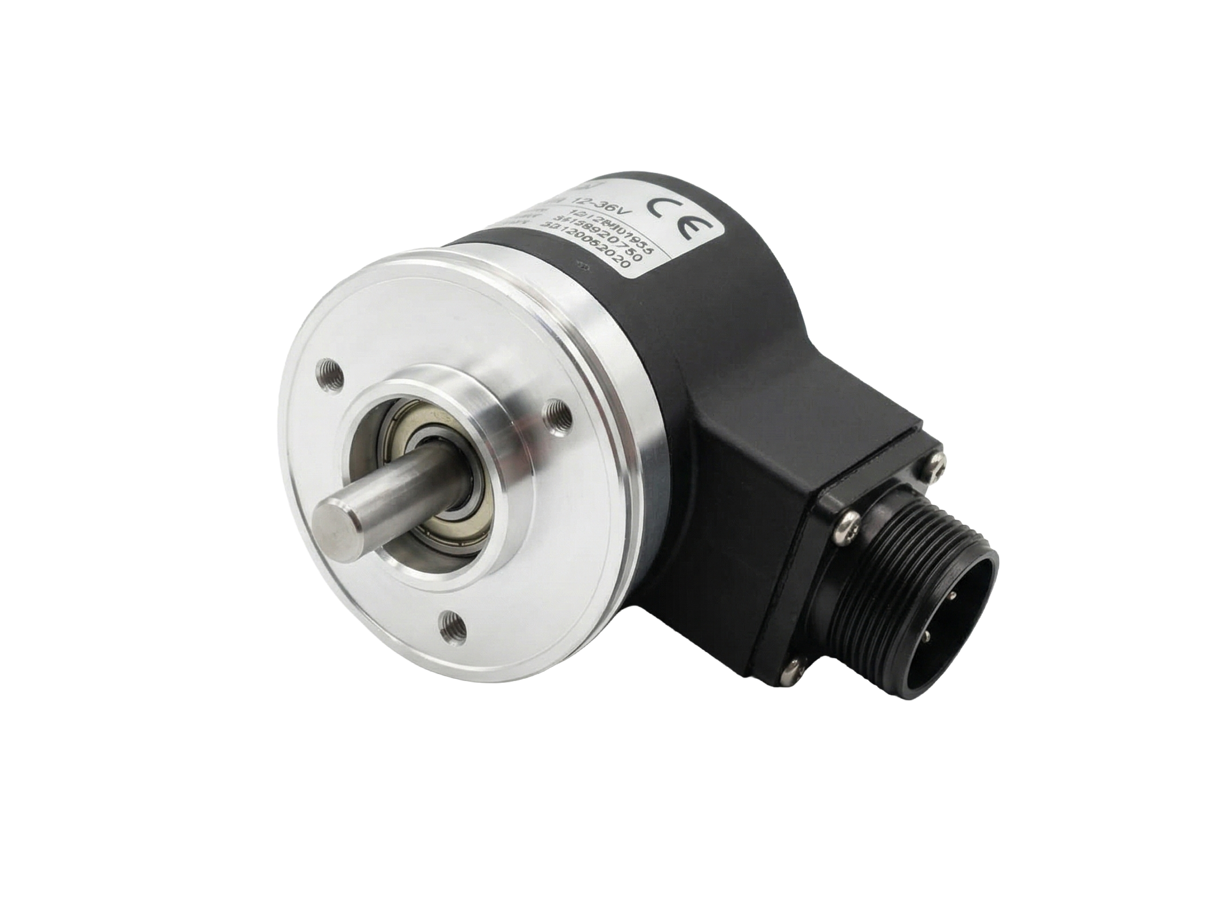
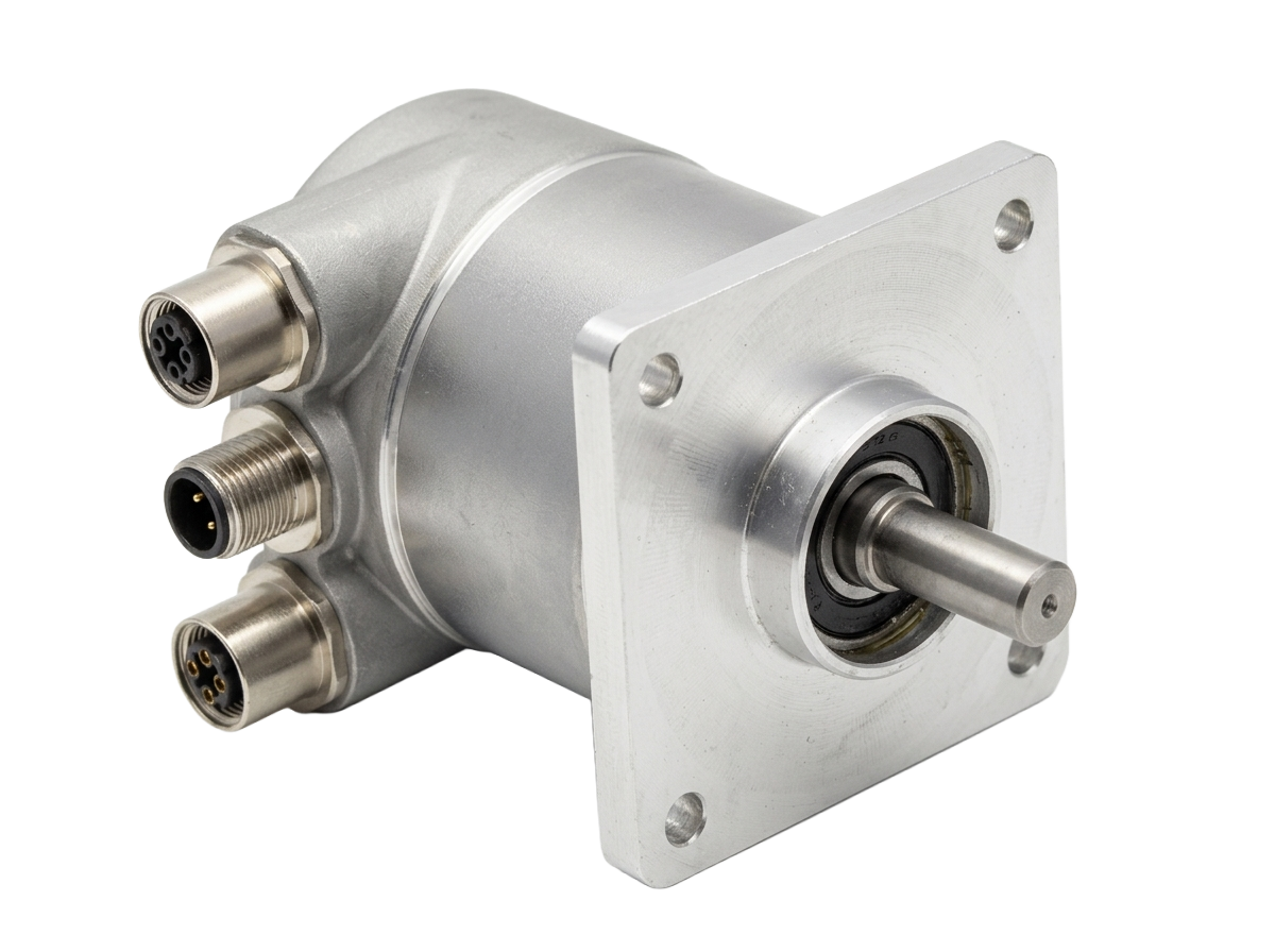
8. Electrical Connection
The type of electrical connection between encoder and system.
| Code | Type | Notes |
|---|---|---|
| P10 | Axial cable 1m | Rear exit, integrated cable |
| PL30 | Radial cable 3m | Side exit, integrated cable |
| PL50 | Radial cable 5m | Side exit, long cable |
| S07 | MIL 7-pin axial | Basic signals, rear exit |
| L07 | MIL 7-pin radial | Basic signals, side exit |
| S10 | MIL 10-pin axial | For Line Driver (LD/LD2), rear exit |
| L10 | MIL 10-pin radial | For Line Driver (LD/LD2), side exit |
| R1 | 12-pin radial connector | Side exit |
9. Output Circuit (Electronics)
The type of electrical signal output — i.e., how the encoder communicates with the PLC or controller. This is the most important segment for electrical compatibility.
Standard outputs:
| Code | Type | Description |
|---|---|---|
| S | NPN standard | NPN transistor, sinking — standard logic |
| OC | NPN open collector | NPN open collector — flexible, requires pull-up |
| P | PNP standard | PNP transistor, sourcing — common in Europe |
| OP | PNP open collector | PNP open collector |
Push-Pull outputs:
| Code | Type | Description |
|---|---|---|
| PP2-5 | Push-Pull 5V | Symmetrical output, 5V supply |
| PP2-1130 | Push-Pull 11/30V | Symmetrical output, 11–30V supply — most used in industry |
Line Driver outputs (differential):
| Code | Type | Description |
|---|---|---|
| LD | Line Driver RS-422 | Differential A/A̅, B/B̅, Z/Z̅ — 5V supply only |
| LD2-5 | Line Driver 5V protected | RS-422 with protection, 5V supply |
| LD2-1130 | Line Driver 11/30V protected | RS-422 with protection, 11–30V supply |
For absolute encoders, outputs are communication protocols: SSI, EtherCAT, PROFINET, Profibus DP, Parallel.
10. Special / Custom
The last segment indicates whether the encoder has customizations compared to the standard.
| Code | Meaning |
|---|---|
| *(empty)* | Standard catalogue configuration |
| CUSTOM | Special version on customer request |
Possible customizations include: special shafts, extended temperatures (-40°C / +100°C), reinforced protection, non-catalogue resolutions, dedicated wiring and adaptation flanges for retrofit.
Complete Example: TK561 - F - 1024 - 11/30 - V - K5 - 10 - L10 - PP2-1130
Let us read it segment by segment:
| # | Segment | Value | Meaning |
|---|---|---|---|
| 1 | Type | TK561 | TK50, bidirectional + Z pulse |
| 2 | Mounting | F | Standard servo flange |
| 3 | Resolution | 1024 | 1024 pulses/revolution |
| 4 | Power supply | 11/30 | +11–30 Vdc (industrial standard) |
| 5 | Frequency | V | Fast, up to 300 kHz |
| 6 | Protection | K5 | IP65 — water jets |
| 7 | Shaft | 10 | Ø10 mm |
| 8 | Connection | L10 | MIL 10-pin radial |
| 9 | Output | PP2-1130 | Push-Pull 11/30V |
The Online Configurator
The fastest way to compose an order code is to use the interactive configurator on every product page. Visually select each parameter and the code builds up in real time. When done, you can download the PDF datasheet or request a quotation directly.